RFID Card Reader Module
Product Description
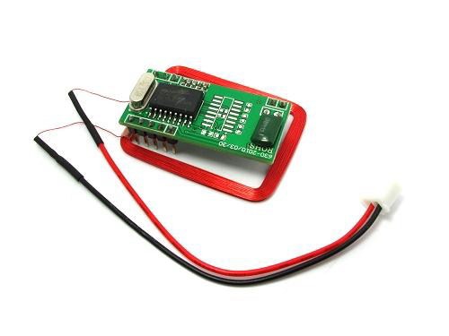
This is an easy-to-use RFID card reader module, designed to read the common EM4100 RFID tags and cards. It has a simple UART output, transmitting the card ID as simple ASCII characters as soon as the card is brought into range.
Pin Description
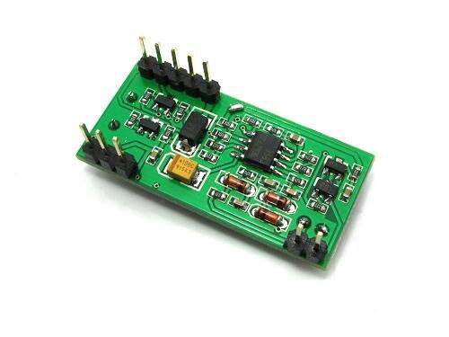
Ports and pin numbers refer to the product image above.
| Port | Pin Number | Name | Description |
| Port 1 | 1 | TX | UART transmit |
| 2 | RX | UART receive | |
| 3 | - | ||
| 4 | GND | Ground | |
| 5 | +5VDC | Power supply | |
| Port 2 | 1 | ANT1 | Coil connection |
| 2 | ANT2 | Coil connection | |
| Port 3 | 1 | LED | Status LED |
| 2 | +5VDC | Power supply | |
| 3 | GND | Ground |
Specifications
| Frequency | 125kHz |
| UART Baud Rate | 9600baud |
| Supply Voltage | 5VDC +5% |
| Operating Current | <50mA |
| Operating Range | >50mm (variable, depending on card/manufacturer) |
| Operating Temperature | -10oC - +70oC |
| Storage Temperature | -20oC - +80oC |
| Humidity | 0 - 95% |
| Physical Size | 38.5mm x 19mm x 9mm |
Output Format
When a card is detected, its identification code is transmitted as 10 ASCII characters representing 5 HEX data bytes, followed by another 2 ASCII characters, representing a HEX checksum byte, as follows:
| 10 ASCII characters | Checksum | |||||||||||
| Transmitted ASCII Byte # | 1 | 2 | 3 | 4 | 5 | 6 | 7 | 8 | 9 | 10 | 11 | 12 |
| Data Byte # | 1 | 2 | 3 | 4 | 5 | 6 | ||||||
The checksum is simply the result of a XOR operation on the preceeding 5 data bytes.
Example
If a card has an ID of (307E4DE5C2)16 , the module will output those exact 10 ASCII characters as represented in HEX. The checksum will be the result of a XOR operation on those 5 data bytes:
(30)16 ⊕ (7E)16 ⊕ (4D)16 ⊕ (E5)16 ⊕ (C2)16 = (24)16
| 10 ASCII characters | Checksum | |||||||||||
| Transmitted bytes (ASCII) | 3 | 0 | 7 | E | 4 | D | E | 5 | C | 2 | 2 | 4 |
| Actual data bytes (HEX) | (30)16 | (7E)16 | (4D)16 | (E5)16 | (C2)16 | (24)16 | ||||||
Thus, the module will output the ASCII characters "307E4DE5C224".

